PIM (Passive Inter Modulation).
This item has been made unavailable per Q1, 2024. The new calculator can be found here.
Passive Intermodulation, also known as PIM, is an unwanted effect where spectral distortion is generated as a result of non-linear effects in a Multi Transmitter (co-site) set up like you find in mobile telephone networks, i.e. base stations. The handling of trafic through a base station is in general handled by more that one transmit frequency. With more than one transmitter active on the site, there is always a serious chance that PIM generation plays a role and that the additional and unwated spectral components are falling into the base stations receive channels.
This noise in the receive channel reduces the base stations capability to handle the traffic as planned because the BER number is increasing. What is the cause of PIM? In the close vicinity of the base station metalic junctions of different materials with different voltaic voltages can cause non-linear and diode like effects in the close vicinity of the transmit antennas as the field strength close to these metalic junctions is quite high.
Analise how non-linear metallic effects can cause inter-modulation signals falling into your RX channels with the WinRFCalc PIM analyser. What are the calculation methods used in this tool:
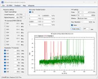
- Define the TX and RX frequencies of the station. This is done by defining the TX frequencies and calculate the RX frequencies by taking the TX-RX offset into account.
- Create a multi tone time domain signal with all the defined channels.
- When the Non Linear transfer function is checked, then during the calculation of the time domain multi tone signal a non linear operation is applied to the time domain signal. This non linear operation is the source of the intermodulation.
- The next step is to run an FFT where the time domain signal is converted from the time to frequency domain.
- In the spectral display the green curve is the RF spectrum calculated by the FFT. The red curves are the channel bounderies which allow you the see if intermodulation components are falling in the RX channels.
- The program does not analyse with power levels and is just frequency driven. You can check with the chosen frequency layout if there are chances of PIM interference.
The PIM analyser will undergo a major redesign a we try to make it available in the upcoming V2400 version.
R